Intro
I highly recommend reading through this entire guide, BEFORE diving into this project.
First off, how do you know if you have a bad wheel bearing? Most likely you’ll hear a loud ‘whirring’-like noise coming from the front end of your car. It almost sounds like you’re on a NASCAR track, zooming around a turn. In fact, if you do go around a turn, left or right, and the sound gets louder or quieter with those turns, you can pretty much bet your hub has gone bad. Additionally, you may feel some vibration in the steering wheel when the sound gets louder around a turn.
Personally, the sound was noticeable at about 25-30MPH and slowly became louder as my speed increased. Around 80, I would have to play the radio at full volume drown it out. If you jack your car up, and move the front wheels by hand, you may be able to hear or feel which one is bad because the wheel will not move smoothly.
If you have to end up replacing one, you might as well replace both as the other side may be close to going bad too.


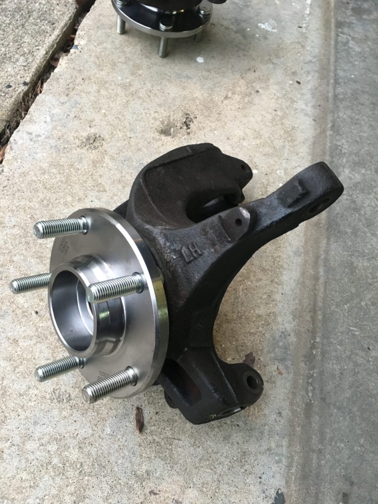
In this guide, I’ll give you step by step instructions on what you need to do to remove a bad wheel hub assembly from your Mazda 3. Unfortunately, with the 2004 Mazda 3, you will need to have access to a 20 ton or more press in order to remove the old wheel bearing assembly and to install the new one. If you do not have access to one, you will need to take it to a shop in order for them to press the old one out and the new one in.
The process described here shows you how to change the front wheel bearing hub. Changing the rear is a similar process, but just make sure you are purchasing the correct assembly, as they are not the same. Secondly, make sure the hub you are buying matches your braking system. You need to have a bearing that is compatible with your ABS sensor. The part number is 513211 for a 2004 3, 2.3L with ABS brakes.
I was able to purchase two Moog assemblies off Amazon for $81.00 per assembly. This was not before I had to return the first pair, because the seller messed up and mixed 513211 and 513212 up with their labeling. Guess who received the non-ABS version? If you’re not sure which is which, just look at the back of the bearing. There should be a black magnetic ring around the back, which is what your ABS sensor will pick up. If there isn’t one, or it isn’t magnetic, then it is not the ABS model.
Last note before getting into the more detailed steps. If your 2004 Mazda 3 was manufactured BEFORE December 2004, your job becomes even more fun. I found this out along the way, but the CV axle in these models uses a bolt-in, rather the screw-on nut assembly to hold the bearing on. You’ll see what I mean in the pictures, but if you have this type of assembly, these bolts are Torque To Yield (TTY), meaning they are a one use bolt.
They stretch as they are torqued down and when removed, they are weakened and not recommended to be used again. Unfortunately, these are also a specialty part. I ended up at 5 different dealerships and 4 different stores to see if anyone carried these bolts. None of them did. They are a specialty order part that not even the Mazda dealership keeps in stock. I had to be on the road within two days and with the holiday approaching I was desperate to get the car put back together, correctly.
You can order these bolts online and have them to you within a few days or you can order them specifically from the dealership. The one other place that was able to order them was NAPA, but they had to be shipped from their supplier. And to add to hassle, these bolts will run about $10-$30 per bolt. For my car, 2004 Mazda 3, 2.3L I used bolt “9YA0-21-083F”. Also, if you need to get a new wheel cap with the Mazda logo on that, it is part number “G22C-37-190A”. It was only about $10 from the dealership for the cap.
Items Needed:
- New Hub Assemblies
- Torque Wrench (This is the one I use)
- Metric Wrench Set
- Metric Socket Set
- Female Torx
- Needle Nose Pliers
- Vice grip
- Crow Bar
- Breaker Bar or Pipe for Leverage
- LocTite
- Anti-Seize
- Penetrating Oil
Torque Specs:
- CV Axle Lock Nut (Mazda’s Manufactured after December 2004) – 173.5 to 202.3 ft lbs.
- Low Control Arm Pinch Bolt – 31.8 to 43.3 ft lbs.
- Strut Bolt – 65 ft lbs.
- Tie Rod Bolt – 27.5 to 37.1 ft lbs.
- Lug Nuts – 65 to 86.73 ft lbs.
- Caliper Bolts – 57.9 to 75.2 ft lbs.
- Sliding Caliper Pin – 19 to 22 ft lbs.
- Stabilizer Control Link – 31.2 to 44.3 ft lbs.
- TTY Bolt – 25 ft lbs. + a quarter turn.
The last two in the list above, aren’t used in this job, but I included them in case anyone plans on replacing brake pads or the control links while doing this.
Disassembly
1) Basic stuff
Loosen the front lug nuts, jack the car up, chock the rear wheels, and remove the front wheels.
2) Remove Spindle Bolt
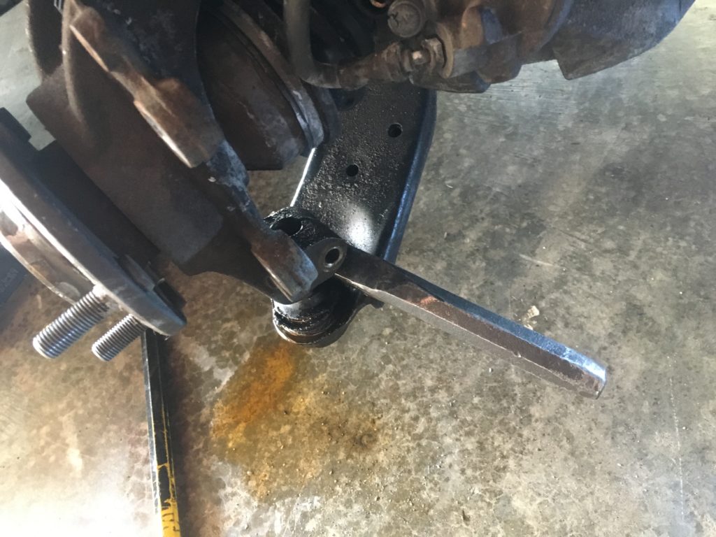
Having someone apply the brakes, use a breaker bar to remove either the lock nut or bolt in the center of the hub. If you got a little ahead of yourself and have already removed the caliper before doing this step (like I did, pictured below), you will need a crow bar or other long piece of metal. Simply place the crow bar in between the threads and leverage it against the ground so you can remove that nut or bolt.
If the nut or bolt doesn’t want to come loose, hit it with a little penetrating oil.
3) Remove the Caliper bolts
Using a breaker bar or pipe over a ratchet, loosen the two caliper bolts behind the rotor. Be careful not to drop the caliper assembly as it is still connected to the brake line. Do not kink, or twist this line. Using a coat hanger, stool, or bungee cords, position your caliper so there is not tension on the brake line and the caliper is out of the way.
If you plan on replacing the brake pads or rotors, now is an easy time to do that.
4) Remove the rotor
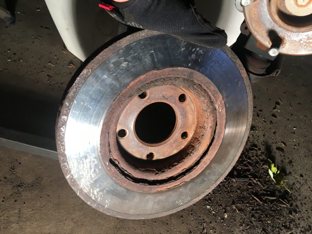
I had just replaced my front rotors a few weeks prior to this, so mine slid off very easily. However, when I replaced the old ones, they did not come off so easily. Living in the Midwest, there’s plenty of rain and salt on the roads to help corrode those rotors on. Since new ones were going on, I simply hit them with a sledge hammer to jimmy them off.

If you can’t do that, apply some penetrating oil to the back and allow them to sit for about 10 minutes. Then hit them with a rubber mallet around the edges or place a 2×4 on the rotor and hit that with a hammer. The rotors should at least be loosened up now, but if they’re not, place a piece of wood or metal in the rear between where the caliper bolts were mounted and hit that piece to try and leverage the rotor off.
If that still doesn’t work, hit the rotor around the front of the face. NOT the part the pads touch, but the area close to the lug nut threads. Continue hitting these areas and gently on the edges of the rotor to free it. Don’t be afraid to apply more penetrating oil, these can be tricky.
5) Remove the ABS sensor
Unhook the wire that runs to the ABS sensor and put it out of the way.
Using a female torx, or a Kobalt Universal socket set in my case, remove the screw holding the plastic ABS sensor in place. Odds are the sensor itself is stuck in there. If it doesn’t move by hand, take a flat head screwdriver and GENTLY tap the end of the screwdriver that is pointed at the edges of the sensor. I put ‘GENTLY’ in all caps, because I hit my too hard and ended up breaking the sensor.
That little piece of plastic will run you an easy $40 at AutoZone. Gently go around the edges of the sensor until you’re able to free it from the knuckle.
6) Remove Lower Control Arm Ball Joint
On my car this was the toughest and most frustrating part. On the bottom of the knuckle there is a pinch bolt which runs along the backside and “pinches” the knuckle onto a ball joint that is connected to the lower control arm. You’ll first need to remove this nut and bolt, but not after blasting it with some penetrating oil.
If you’re as unlucky as I am, then you’ll find the nut comes out, but the bolt may not want to budge. You may have to take a hammer to get the bolt to move, but make sure you put the nut back on first. Place the nut so it is flush with the end of the bolt, so you don’t end up damaging the threads. If you’re luck continues to go south like mine did, you may hit the bolt so hard you end up stripping out the threads in the nut. If this happens, you will want to take that bolt to a specialty fastener store and get one that matches the diameter and strength grade.

The bolt that I broke, was rated a 10, so I replaced it with a 10.9, which is actually stronger than the original. You can’t just go to Home Depot or Lowe’s to get a bolt there, you need to make sure you get a bolt that can handle the stress and load of an automotive application. I couldn’t tell you the width of it, but I had the guy at the specialty store measure it with a digital caliper to make sure it was a correct fit.
After removing the bolt, you will need to get some leverage between the lower control arm and knuckle. I had coated this area in penetrating oil multiple times, and it ended up taking me about 1.5 hours before I was able to separate the two. You will need something, like a solid steel chisel, to wedge between the control arm and knuckle. Then standing out of the way, in case the chisel wants to go flying, hit it very firmly and make good contact. Did I mention eye protection was a good idea here?
After you do this enough times, you should be able to free it up. It may take you 20 minutes, it make take you 2 hours. For me, one side was quick, the other side took forever. Additionally, you may need to jack up the knuckle by the bearing, so the control arm will not bounce down when striking it. Again, wear eye protection, and stay out of the the chisel’s flight path.
Avoid damaging the ball joints and check them for any cuts in the rubber after removing the knuckle. A lot of times these will need to be replaced, but this wasn’t in the budget for me this time, so I have to let them go for a bit.

7) Disconnect the tie rod
The tie rod is what controls your steering and to remove this you will have to remove a small pin and break the bolt loose. Bending the pin with needle nose pliers, pull the pin out of the hole in the threads. If you haven’t already, apply penetrating oil to this area and use a breaker bar to break this nut free. Remove the nut, and try to gently tap the rod’s threads down. If that doesn’t work, you will need to jimmy the knuckle around and tap it with a hammer to angle it correctly for the tie rod to be removed.
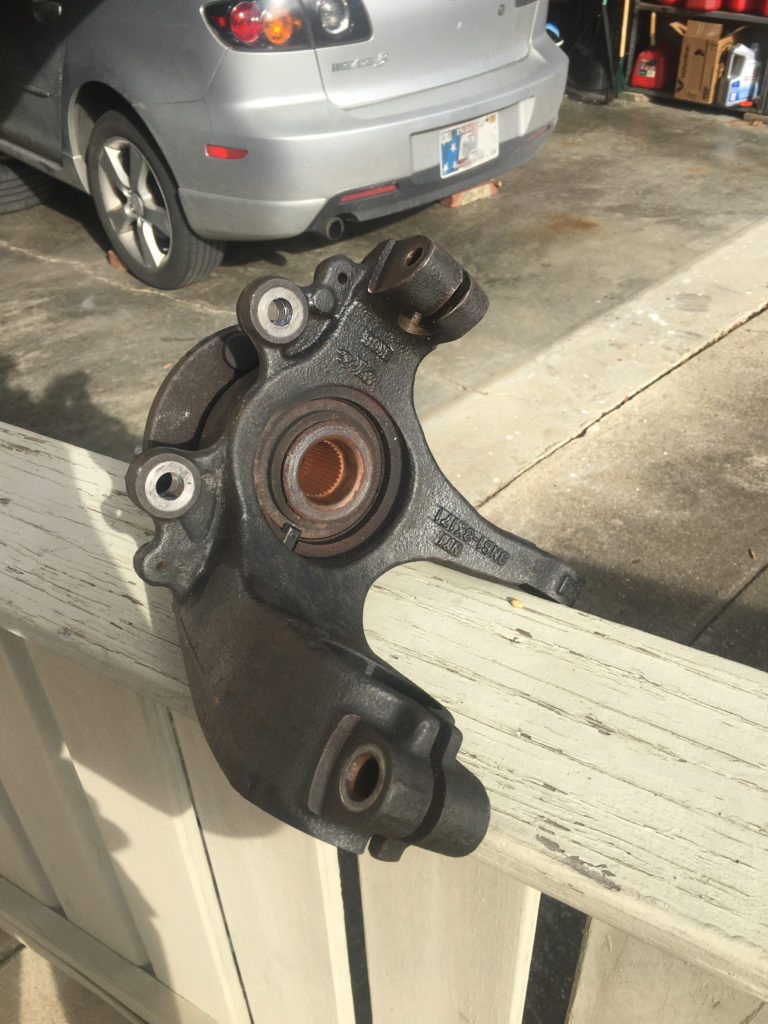
8) Remove the knuckle assembly
Behind the strut there is a bolt that holds the knuckle in position. Blast this area with penetrating oil and all around the area where the strut goes into the knuckle. In fact, try to do this the night before if you can. This area sees a lot of water and that can cause the strut to become very difficult to get off. I had replaced my struts about 2 months prior to doing this job, so mine came off very easily.
After breaking the bolt free, take a sledge hammer and hit the top of the knuckle to free it from the strut. This will take a lot of strikes before the strut will move, so don’t get discouraged too quickly. Apply more penetrating oil as needed.
9) Press out the old and press in the new
Now that you successfully have removed the knuckle, you will need to press out the old bearing and press in the new one. If you have a shop press, great! If not, call around to some local shops and see who can do it for you. I ended up paying about $60 at a tire shop to do both front ones. It shouldn’t take them more than an hour to do, in fact, mine only took 30 minutes.

10) Clean all the parts
One thing you will want to do before re-installing is to clean everything out with a wire brush and apply anti-seize and/or LocTite where appropriate. Thoroughly clean all bolts, threads, nuts, crevices, etc. with the wire brush to remove any gunk that may have found its way in there. It’s also not a bad idea to blow some compressed air in the ABS sensor connections.
Personally, I apply anti-seize to any areas where I would have to use penetrating oil to help remove parts. This includes in the knuckle, around the part of the rotor where the new knuckle will be in contact with, unthreaded parts of bolts, etc. I also applied blue LocTite to all the bolts I reinstalled, except the lug nuts.
Re-installation
Re-installation is fairly straightforward and just doing the above steps in reverse order. I’ll briefly go over these steps along with some helpful hints. Also, as I mentioned above, don’t forget to apply anti-seize and LocTite to the appropriate places. Mazda has a window of recommendations for torque specifications. Be sure to use a torque wrench that has been properly calibrated and torque to your car’s specifications.
11) Reinstall rear strut bolt
Set the knuckle on top of the lower control arm and re-position the knuckle so it is in line with the strut. There is a piece of metal in the shape of a hook on the back of the strut that you will need to line up. Using a jack, jack the knuckle up back into the strut and replace the bolt in the rear. Torque this to 65 ft lbs.
12) Insert the CV Axle
Insert the CV axle back into the bearing assembly and loosely tighten the bolt or nut back on. Again, if your Mazda was manufactured prior to December of 2004, you will need to get new bolts from the dealership or on Amazon here. These are one time use bolts and cannot be reinstalled.
13) Reinstall lower control arm
Now that the strut has been reconnected, line up the ball joint on the lower control arm, and tap it into place with a hammer. Once lined up, hammer this piece back into place, or use a jack to help you. Reinstall the nut and bolt and torque to 40 ft lbs.
14) Reconnect the tie rod
If you need to, adjust your steering wheel to line up the tie rod into its hole. Using a ratchet tighten the nut as far as you can go. You will likely need to use a pair of vice grips to hold the bottom part from spinning will you tighten the nut on top down. After tightening the nut, and torqueing to 35 ft lbs. Reinstall the pin and bend it to its original shape.
15) Reinstall the ABS sensor
Be sure you have cleaned the area where the ABS sensor will go. Place the ABS sensor back in its spot and gently tap into place. Reconnect the ABS wire.
16) Reinstall rotors and caliper
Place your rotors back on and reinstall the caliper. During this disassembly and reassembly, avoid pressing the brakes after the calipers have been removed. This makes it much more difficult to reinstall. However, in case you have applied pressure to the brakes and the brake is no longer compressed you will want to use a brake compressor tool, so you have enough space to reinstall.
Otherwise, you will need to do this trick. Place two or three lug nuts on only the rotor and loosely tighten. Take out the brake pad closest to you and reinstall the caliper. Looking at the side of caliper, that allows you to check the life of the brake pad, stick a rod, or chisel in here so you can apply leverage to the caliper. This should compress the caliper, but be careful as to not damage the rotor. Remove the caliper and lug nuts, and reinstall everything as your normally would.
Torque your caliper bolts to 70 ft lbs. and clean the rotors with brake cleaner.
17) Tighten Axle Bolt/Nut
Applying the brakes, torque the axle nut to 200 ft lbs. If you do not have an axle nut, but have the bolt version like mine, ask your dealership what the specs are. I believe it is 25 ft lbs. and then another 90 degree turn, but that was after some Googling on unverified sources. Reach out to the dealership to be certain.
18) Reinstall wheels
Reinstall your wheels, lower the vehicle, and torque the lug nuts back to 85 ft lbs. in a star pattern.
Extra Notes
You may notice that your ABS light stays on, don’t worry. After driving around for a little bit, it should go off.
If you have any other questions, or are in need of assistance, feel free to leave a comment below!


I hope you don’t take this personally- I appreciate the effort you made to help others by doing this article.
You mention two manufactured dates in the article- before / after 2014 and before / after 2004; do you mean 2004 in all instances? The first one (in the paragraph starting “Last note before getting…” says if the 2004 Mazda 3 was made before December, 2014- which it obviously was- and the second one is in the torque specs, saying if it was manufactured after December of 2014. Step twelve states 2004, which I believe to be the correct year (also, the plural of Mazda is Mazdas- no apostrophe { ‘ } between the “a” and “s”), and thanks for publishing the torque specs.
Otherwise, thanks for a detailed write-up.
Daniel
Daniel – Good catch. I think that is a typo. I will update this. Thank you for tactfully pointing that out. I started writing this article not long after getting the job done, so to say I felt brain dead is an understatement.
Wow! Excellent source of information. I like the way you conveyed a complicated topic.
i gotta say, precise and detailed for my project. appreciate it very much – good job on the pixs too, clean and clear for me to see and compare. thank you!!
I have a question about the bearing/hub assembly installation into the knuckle. Did they just press it from the outside of the hub? or did they need to use a special tool to press from the outer bearing race?
A few things if you don’t mind. The bolt was used up to 5/2005. Mine was manufactured in 4/2005 and has the bolt and press in bearings. Mazda 3i 2005. That said, I have a 12 ton shop press and pressed the bearings and hubs in easily. I can’t think of why you would need a 20 ton minimum press. The lower ball joint with the pinch bolt. Yes they can be a pain, but driving a steel chisel of sufficient size in between the ears on the knuckle allows them to open a bit and the ball joint to fall right out. A pickle fork available from harbor freight or any auto parts store is another option. Just watch your ball joint boots if you plan on reusing the ball joints.
Thank you for putting this up. Must have taken some time. Should be very helpful to those doing it for the first time.
Thanks for the info Tim, this is very helpful information!
i’m way late, but this guide helped me massively! thank you, now i know that i need a press to replace my bearings 🙂