Materials Needed
- 60A Breaker
- #6 Gauge Wire
- 3/4″ Conduit/EMT
- 3/4″ EMT Fittings
- 3″ Deck Screws
- 2.5″ Deck Screws
- Electrical Tape
- Tesla Wall Charger
- Disconnect Switch*
Tools Needed
- Drill or Impact Driver
- Voltage Detector
- Stud Finder
- Wire Cutters
- Drill Bits
- Flat Head Screw Driver
- Phillips Head Screw Driver
- Conduit Cutter
- Conduit Bender
- De-burring Tool
Intro
I live in the US in a residential area in a house that was built around 2014. So depending on where you live and how old your house is, your install situation may be slightly different than what I’m about to show you. I am installing a 60 amp breaker so I can get the maximum amount of power to charge my Tesla model 3.
You may choose to install a lower amp breaker, but you will get lower charge speeds as a result. The table below shows the respective charge rate for each breaker’s rated amperage.

These are the charge speeds for the gen 3 wall connector. *Maximum charge rate for Model 3 Standard Range is 32A (7.7kW) – up to 30 miles of range per hour. Source: https://www.tesla.com/support/home-charging-installation/wall-connector
You’ll notice the circuit breaker needs to be rated higher than the max output of the wall connector. This is to account for continuous use and allow for any small surges in electricity without tripping the breaker.
Once the charger is plugged into the car, you can always adjust the draw from the charger lower. For example, if you install a 50 amp breaker that has a max output of 40 amps, you can charge at 32 amps or lower by adjusting it in the car.
However, because the breaker has a max rating of 50 amps, anything greater than 40 amps will trip the breaker and cause the power to shut off.

These are the charge speeds for the gen 3 wall connector. *Maximum charge rate for Model 3 Standard Range is 32A (7.7kW) – up to 30 miles of range per hour. Source: https://www.tesla.com/support/home-charging-installation/wall-connector
5 Things to Check Before Starting
There’s a few things to check before heading out to the home improvement store or even purchasing the home charger. I encourage you to watch the entire video or read the entire article from start to end before doing ANYTHING.
My personal saying is that, “No DIY project is complete without at least 3 trips to the home improvement store.” So plan ahead so those 3 trips don’t turn into 6 trips.
Here’s what you’ll need to do.
First, check and make sure you have at least 200 amp service to your home. Then figure out how to get access to your circuit breaker box to run additional wire. If you do not have at least 200 amp service to your home, this is something you’ll want to consider.
Why do I need 200 amp service?
If you are in a situation where the AC is running, the stove is on, along with other appliances that draw a lot of electricity and you try to charge your car – this could cause the main breaker to trip. Regularly tripping the main breaker in home not only shuts off all electricity to the home, but is a sign you regularly using more power than your home is rated for.
See this article for upgrading your home to 200 amp service. Spoiler alert, it usually costs at least a few thousand dollars and you’ll need to get your local electric company involved.
Third, figure out what kind of circuit breaker box you have, so you know what breaker switch to buy. This is important so you purchase the correct breaker. One easy way to ensure you purchase the correct one is to shut off the power, then remove one of the ones currently installed on your system to take to the store with you.
Then, if you plan on running a line straight from your main circuit breaker box, local code may require you to install a disconnect switch. What this means is there has to be a mechanism for disconnecting power to the charger that is separate from the main box. Your air conditioning unit likely has one of these.

Insert picture of a disconnect switch here
For me, I already have a subpanel set up that has a circuit breaker switch in it.
Do your own research and find out if your municipality or local code requires it. You don’t need to install a full sub-panel like I have here, you can run a box with a disconnect switch that costs less than $20 from Amazon or Home Depot to do this.
They typically are labeled to be used for air conditioners. From what I’ve found googling around online it deals with “Code 86-304 Disconnecting Means,” specifically with circuits that are 60 amps or greater.
Amazon recommendsSquare D’s QO200TRNM 60 A Non Fuse Disconnect
I’m not an electrician so do your own research and if you’re not 100% sure, call an electrician.
Lastly, consider future proofing this install, especially if you already have plans on purchasing a second electric vehicle.
How do I future proof my Tesla Wall Connector install?
Let’s consider your spouse wants to purchase a Tesla (or any other electric vehicle) after having driven yours. While you can pass off one charger between vehicles, having 2 makes charging much more convenient.
In my opinon, there are two ways to future proof your install.
1. Run a sub-panel like I have in my setup.
2. Run an additional line of conduit or wire from your main circuit box as if you were installing the charger second charger now.
The first option provides you a lot more flexibility in the long run, which is why I had it done in the first place. By running a sub-panel, you can install more than just a charger. If you want some additional lights in your garage, maybe a few more outlets, or even 220V/240V for specific tools, then this is the way to go.
A sub-panel typically only costs a few hundred dollars in materials and for 99% of people it’s the last time you’ll ever have to get into the main circuit breaker box for wiring.
The second option is to go ahead and install a second 60A (or whatever size breaker fits within your energy demand) in the main circuit breaker box and set up the conduit. Then whenver you’re ready to install your second charger, run the wire and connect to the breaker.
I’ll have a more detailed post and maybe a video for this topic by April 1, 2021.
Where do I put the Tesla Wall Charger?
After you’ve checked those 5 things, let’s get started with planning and installing the charger.
Decide where you’ll be mounting the charger. I am going to be placing this piece of oak hardwood with a walnut inlay behind mine as a decorative piece and to make it easier to mount.

Picture of the oak, walnut board
However, it still needs to be connected to a stud in the wall. The maximum height it can be mounted is 60” from the floor, with a minimum height of 18” indoors and a minimum of 24” outdoors, as stated by Tesla.
I’ll be placing my charger right next to my sub-panel and next to this shelf. Keep in mind this charger will need to connect to wifi, so you may want to double check on your phone that you have a wifi signal that reaches where you’re installing the charger. If not, consider purchasing a wifi network extender or relocating the charger.
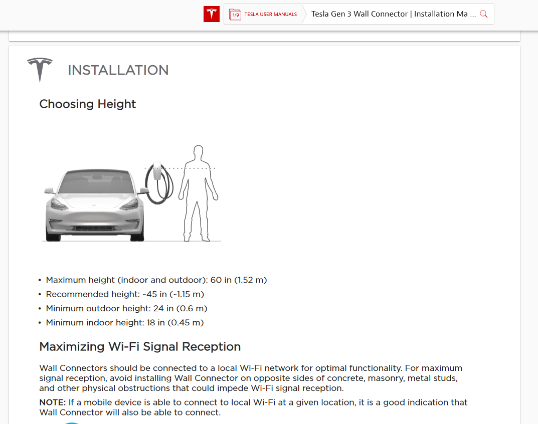
Tesla recommendations for height as shown in the manual.
Running Conduit to the Charger
Now decide how you’re going to run conduit from your box to the charger. Tesla provides instructions for running conduit to the bottom, top, or rear of the charger. If you’re running it through the rear, you’ll need to drill out holes to accommodate the wiring. Otherwise, the top and bottom holes on the charger have a gasket that pops off and fits ¾” conduit by default.
I am going to run conduit to the top of the charger, from the side of my sub-panel.
Map out your path from the box to charger, and start making any bends you need to the conduit.
If you need to bend metal conduit, you’ll need a conduit bender. There are plenty of other videos out there on how to bend metal conduit or you can use pvc. If you’re placing the charger outdoors, you will want to check what you need to use to stay up to code.
To give myself a little bit of wiggle room, I’m leaving some extra length on each side of the conduit, so I can trim it down and dial it in if needed. Now I’ll do a quick test fit to see if it’s roughly where I need it to be.
Before attaching the conduit to the box, I’m going to remove the back of the wall charger and center it on the oak and walnut.
Make sure you have deburred both ends of the conduit with a deburring tool.
I recommend theAFA’s Deburring Tool with 10 Removal Blades
Mounting the Wall Charger
From the looks of the included instructions you can use the holes along the top and bottom of the charger, so as long as they match up. It looks like it’s made this way to give you flexibility in how you mount it to the stud.
However, since I’m attaching it to this piece of wood, I’m going to use 4 holes total for a secure fit. First I’ll line everything up, pre-drill the holes, and attach the back. Then I’ll line the piece of wood up on the wall over where I estimate the stud is, make sure it’s level, and mark the 4 corners on the wall.

Picture of the oak, walnut board
Using a stud finder, I’ll mark the edges and/or center of where the stud is showing. Then I’ll check the surrounding area with the stud finder to make sure there are no live AC wires there.
I use this nail technique to find the true center of the stud. Stud finders can be inaccurate and framing lumber never truly runs straight, so this assures me I am putting a screw dead center.

You can see I start to the outsides of where the edges indicated by the stud finder are and then move in closer until hitting the stud.
Start by hammering a nail into the drywall gently until you creep up on the stud. Once you find one edge, keep going across until you find where the nail pushes through easily. Find the middle distance between those two holes and you have the center of the stud.
Now I can make a mark in between the middle of the corner wood markings. I’ll line the piece of wood up again, make a small mark where the stud line on the wall is showing and draw straight down to the bottom mark. This will be accurate enough for me.
Now I can accurately drill 2-3 holes in the wood and then attach it to the wall.
Finally, I’ll reattach the back of the wall charger and move on with the rest of the setup.

The red circles show where the wood is attached to the stud in the wall. The blue circles show where the tesla charger is connected to the wood.
If you don’t mount the wall charger on a piece of wood, it’s as simple as finding the center of the stud, using the template to mark holes on the wall, and attaching the back.

If you choose to mount directly to the wall, this image from the manual shows you where to place the 2 included screws.
Opening the Breaker Box
At this point, you should have the conduit bent and ready to screw into place and the backplate of the charger connected to the wall.

Here’s where you should be up to this point. My main breaker is shown in red and the sub-panel shown in blue.
Take your voltage detector and place it near any outlet or device that you know has power. This is to ensure that your voltage detector is functional and working. If it’s not, go get one that is.
Now we’ll turn off the power to the box and take the faceplate off.
CAUTION
Work under the assumption everything is ‘live’ until proven otherwise. Do not assume that every single breaker switch and your voltage detector is working. Double and triple checking everything is safe is a must when working with electricity.
Start by turning off all the power to your circuit breaker panel. For me, I am only turning off the power that goes to my subpanel. If you turn off the circuit breaker panel in the main one, shown in the inner red rectangle, cuts off electricity to the entire house. Be sure to do this in the daylight or have a flashlight on and ready.
If you do not have a sub-panel, you will need to turn off the electricity to the main panel through the main breaker.
Now, using a screwdriver, remove the face of the circuit breaker box. Inside you’ll be able to see the two bus bars that run along the middle and all the circuit breakers that are connected to them. Do not touch these. This is where all the electricity leads into your home.
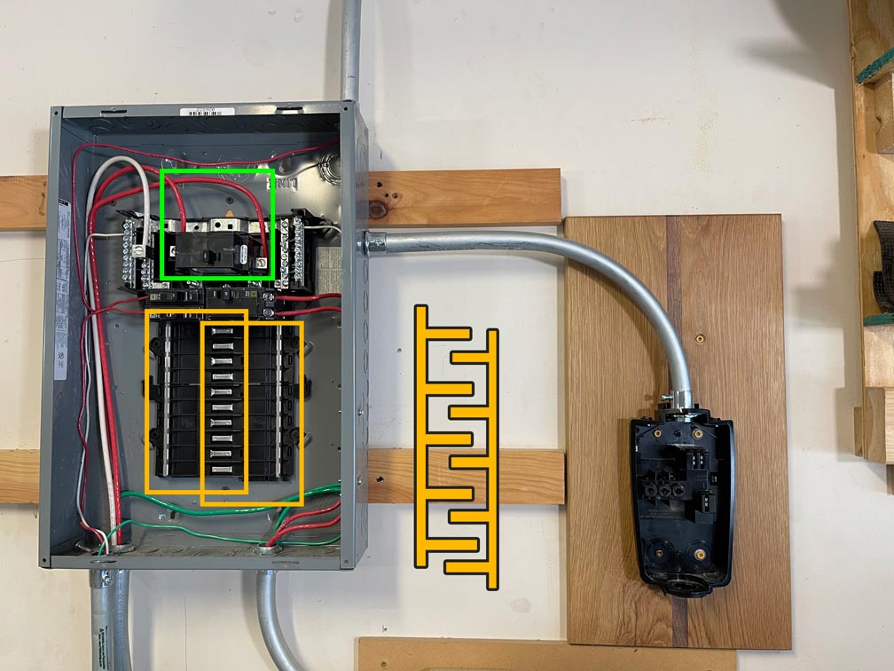
The bus bars in the yellow boxes are what supply the breakers electricity. They are configured as shown in the diagram on the right. They have a sort of zipper design so you can connect a 2-pole breaker to both bars at once. The wires boxed in green are what lead to the main panel and supply this sub panel electricity. Each bar in yellow supplies 120V.
The wires leading out of the circuit breakers are what lead to the outlets, lights, etc. in your home.
CAUTION
Double check the circuit is completely off with your voltage detector. Just because the switch says it’s off, doesn’t mean it’s off – the switch could be faulty.
Now that everything is off and we’ve double checked it, I am going to punch out one of the holes on the side of the box and attach the conduit. Then I’ll attach the conduit to the wall connector and make any trim adjustments to the conduit as needed.

You will need some pliers to completely pull off the perforated holes covers. You can see there are plenty of different options for running wire along the top, bottom, and sides of the sub-panel.
Running the Wire
Once the conduit is firmly in place, I’ll take my 6 gauge wire in red and green and trim off about half an inch of insulation.
Some people may use black and green, but I choose to use these 3 since it’s consistent with my current wiring. In my wiring, green is my ground, red is hot, and white is neutral. Red and black are most commonly your hot wires with white as your neutral and green or a bare, un-insulated copper wire as your ground.
PRO-TIP
You could also choose to run 6GA Romex. ‘Romex’ is simply a brand name for wire that’s already been sheathed together to make for a faster install for electricians, rather than using loose wire like I am. It may be easier to work with depending on how far you are running wire. You may also notice the copper wire is bare – that is okay and it’s supposed to be that way.
If you don’t know which is which in your setup, do not guess – call an electrician.
You can work with solid or stranded – I chose stranded because that’s all Home Depot had. Just make sure it’s 6 gauge or thicker for a 60 amp install.
PRO-TIP
Stranded is easier to push through multiple bends, however with my setup I would have preferred solid. Solid wire is be easier to screw down in the back-plate and in the breaker switch in my opinion.
You’ll need 3 separate wires, 2 red and 1 green. Be sure to make them long enough so that you have plenty of excess to work with on both ends. Strip about half an inch of insulation away on each end of wire.

A piece of 6 gauge stranded copper wire that’s been stripped about 1/2″.
Loosen up the terminals on your 60 amp breaker switch and insert the two red wires into the terminals. Tighten them down until they’re secure. Run all 3 wires through the conduit and connect the ground wire to the ground bus bar.
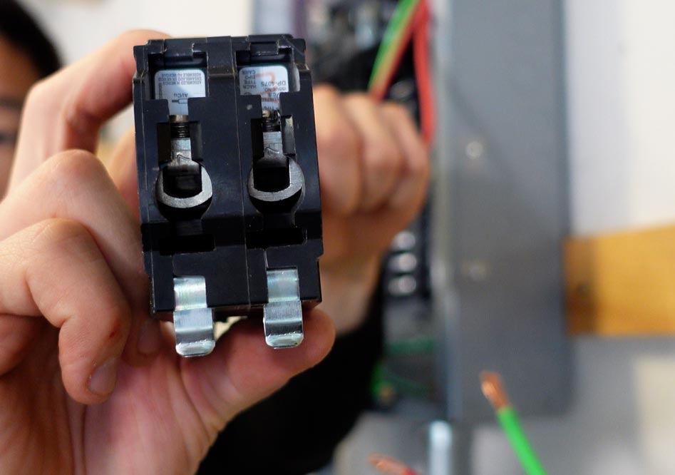
The ends of the red wires can screwed down into the terminals on the 60 amp breaker shown above.
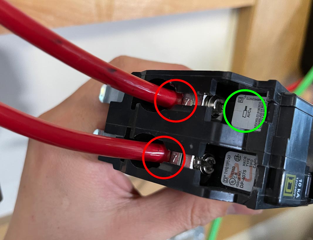
Ensure the insulation is flush to the breaker so no copper is exposed. Be sure to double check that you are using the correct wire as indicated by the sticker in the green circle.
Attaching the 60 amp breaker
Now take the 2-pole 60 amp breaker with your two hot wires and attach it to the bus bars. It’s called a 2-pole because the breaker attaches to the two bus bars in the breaker box.
Remember that this wall charger requires 240v. Each of these poles provides 120V, so when you combine 2 of them together, it provides the full 240v and completes the circuit.
Unlike other wiring you might see in your breaker box, this does not require a neutral wire – the white wire in my setup. For a single pole, like you see for the majority of outlets you have in your home, the neutral wire completes the circuit.
If you want to learn more on this, I’ll link a video up in the top right hand corner that fully explains how this works in the US and Canada.
ven though I know everything is off, I still try to avoid touching any of the non-ground bus bars to be extra safe.
As I mentioned earlier, you’ll need to purchase a breaker switch that is compatible with your box. Mine in this case is Square D. The easiest way to do this is to match up the configuration with one online and then pick it up in store. I actually purchased the wrong Square D breaker switch while at Home Depot by accident.
You can see on mine there are two bars that run along the inside and outside. Mine requires prongs that attach to both of these bars for the electrical current.
Attaching a 40 or 50 Amp Breaker
Installing a 50, 40, or lower breaker is the exact same as above, you will need a two-pole breaker for each each other increment to get 240V. I would suggest running 6 gauge wire regardless, that way if you ever decide that you need more power, the wiring is already set up for it. For a garage setup, the cost is relatively negligble for using 6 gauge wire vs. something smaller.
PRO-TIP
For most, it doesn’t make much financial sense to install anything below a 60 or 50 amp breaker. Apart from aesthetics, the whole reason for installing the wall connector is to get the fastest charge speeds at 34, 44, 30, and 42 for the S, 3, X, and Y respectively. A NEMA 14-50 outlet provides the same charge speeds as a 40 amp breaker at a fraction of the cost.
Wiring the Wall Connector
Ensure the breaker switch is firmly in place and then move onto the wall connector plate. I’m feeding the wires into the terminals according to the diagram in the instructions and then securing them into the appropriate terminals. It does not matter which red goes into which L1 or L2 slot.
Double check to make sure no excess wire is hanging out past the terminal and could possibly touch.
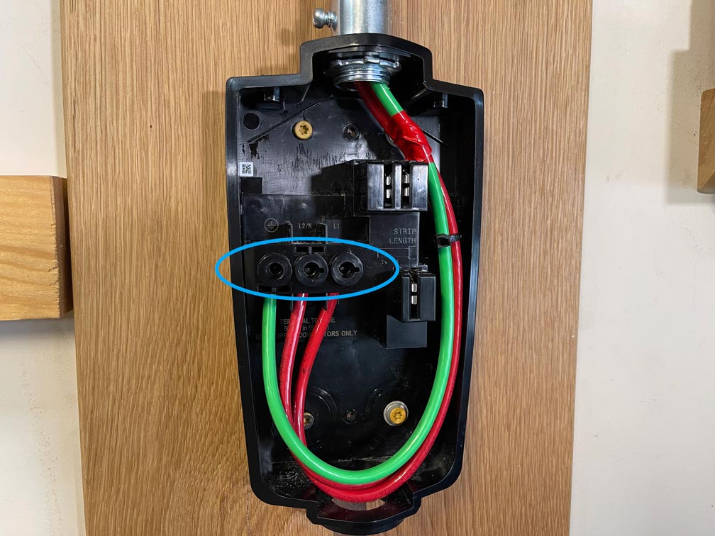
You will loosen and tighten the terminals as shown by the area in blue. I have added some additional electrical tape to the wires that wrap around the top corner. I lightly sanded that corner as it sharp and could rub against the wire.
Attach the zip tie into the hook on the right.
Go back and double check that all the connections you have made in your main breaker, your sub-panel, and/or the disconnect switch are secure. Ensure there is nothing loose, nothing has been knocked out of place, and there is not any scrap wire, tools, or anything else left in the boxes.
After verifying everything is secure and in its place, attach the rest of the wall connector onto the back plate. Add the four screws as directed in the instructions.
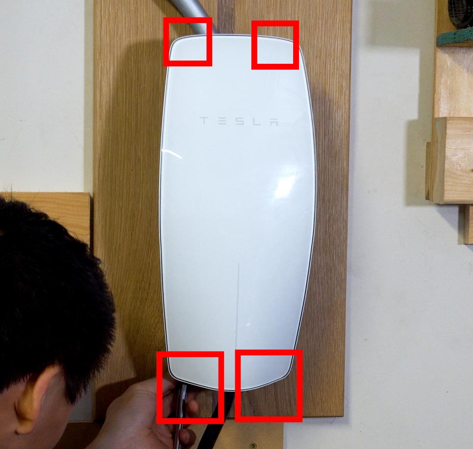
There are 4 screw locations to attach the charger itself to the back plate already mounted on the wall.
Knock out two slots on the panel cover for your circuit box and screw it back into place. Turn on the main breaker, then turn on each breaker switch downstream.
If everything has gone correctly, you should see the wall connector start lighting up. And that’s it – that’s how I installed my Tesla Wall Connector.


